Basic Description: 2D Fourier is a way to filter data by deconstructing it into different frequencies. Something that occurs periodically at a certain frequency, such as plow marks from a farmer's field, can be isolated and removed or subdued.
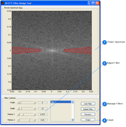
Technical Details: 2D Fourier creates a power spectrum of the selected data. When you click on the Filter button you can view the power spectrum and design one or more filters to mask out areas in the spectrum. When you click Finish, the mask is applied to the filter and used to do a reverse transform, creating the new survey with the masked features removed.
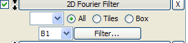
Instructions: After choosing a selection method and making your selection on the survey, click the Filter button to open the 2D FFT Filter Design Tool, where you can create filters. Then finish and run the operation stack. See numbered instructions below
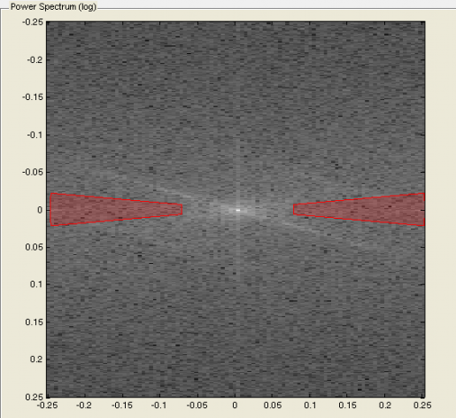
 Power Spectrum
Examine the Power spectrum and look for any features that might correspond to the patterns in the spectrum. Usually periodic linear features present as bright spots or lineations in the spectrum. Lineations usually trend in the opposite direction than they appear in the original survey. The center of the power spectrum represents the lowest frequency events, with increasing frequency going outward from the center. Drawing filters closer to the center will remove lower frequency signals, such as widely-spaced, broad lineations; while filters blocking out signals toward the edge of the spectrum will remove higher frequency patterns, such as closely-spaced furrows.
|
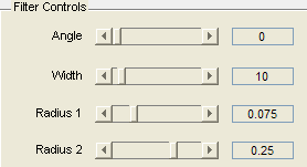
 Adjust Filter
Use the Filter controls to create the filter. You can adjust the slider bars or enter parameters with your mouse and watch the filter change in the power spectrum. The angle parameter determines the orientation (between 0 and 180 degrees) of the wedge filter. The width parameter determines the opening angle of the wedge in degrees (between 0 and 180). Large numbers open the wedge and remove more frequencies. Radius 1 is the inner radius of the wedge; Radius 2 is the outer radius. While the angle and width parameters are used to specify the orientation of the lineation to be removed, these parameters are used to which frequency band is removed.
|
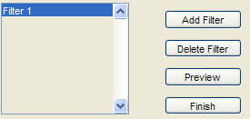
 Manage Filters
Sometimes more than one filter is needed to remove discrete portions of the spectrum. You can add and delete filters using the filter control buttons. To change a filter using the filters controls, click on the name in the list and then adjust the controls on the left.
|
 Finish
Click finish when you are finished designing your filter, then run the operation stack. You can always open the operation and click the Filter button again to adjust the filters. Use the Difference Button to see exactly what features were removed by your filter(s).
|